
In a world where cloud technology is at the center of everything, having a secure, scalable, and well-structured network is essential. The hub-spoke topology in Azure is a great way to manage network traffic efficiently, connecting shared services in a central hub with various workload environments in separate spokes. This guide explores how to set up a hub-spoke virtual network architecture using Azure Virtual Network Gateway.
Let’s dive-in!
Understanding Hub-Spoke Architecture
The hub-spoke model is a network design that helps organize and control traffic flow in a structured way. In this setup, a central hub connects to multiple separate networks, known as spokes. The hub typically hosts shared services like firewalls, VPN gateways, or domain controllers, while the spokes contain different workloads or applications. This approach improves security, reduces costs, and makes it easier to manage network communication across different environments.
Advantages of Hub – Spoke Model
- Enhanced Security – Centralizing shared services in the hub makes it easier to monitor and enforce security policies.
- Cost Efficiency – Reduces the need for duplicate resources in each spoke, lowering overall expenses.
- Improved Performance – Organizes network traffic efficiently, preventing unnecessary data transfers.
- Scalability – New workloads can be added to the hub without major network changes.
- Simplified Management – A structured design makes it easier to control and maintain network communication.
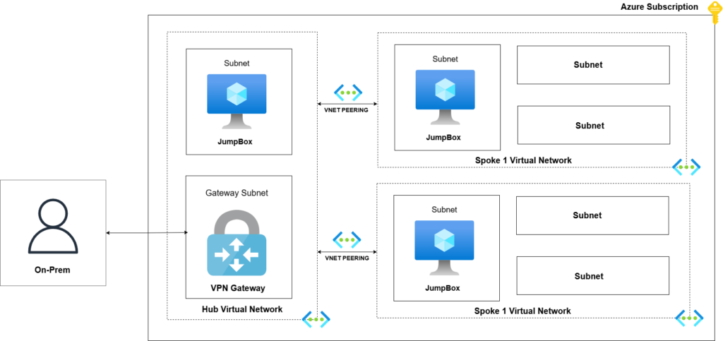
Step-by-Step Implementation of Hub – Spoke Model
1. Creating the Hub Virtual Network — The Foundation of Our Architecture
- Go to the Azure portal and navigate to Virtual Networks.
- Choose your Subscription, Resource Group.
- Now give the name to this VNET “HUB”.
- Do not change anything under the Security tab for this set-up.
- In IP Addresses tab choose, IP address range the you want. (default 10.0.0.0/16)
- Click on the + Add a Subnet.
- Choose the subnet purpose to Virtual Network Gateway.
- Choose the preferred IP Range.
- Now click on review + create.
Now the hub is ready.
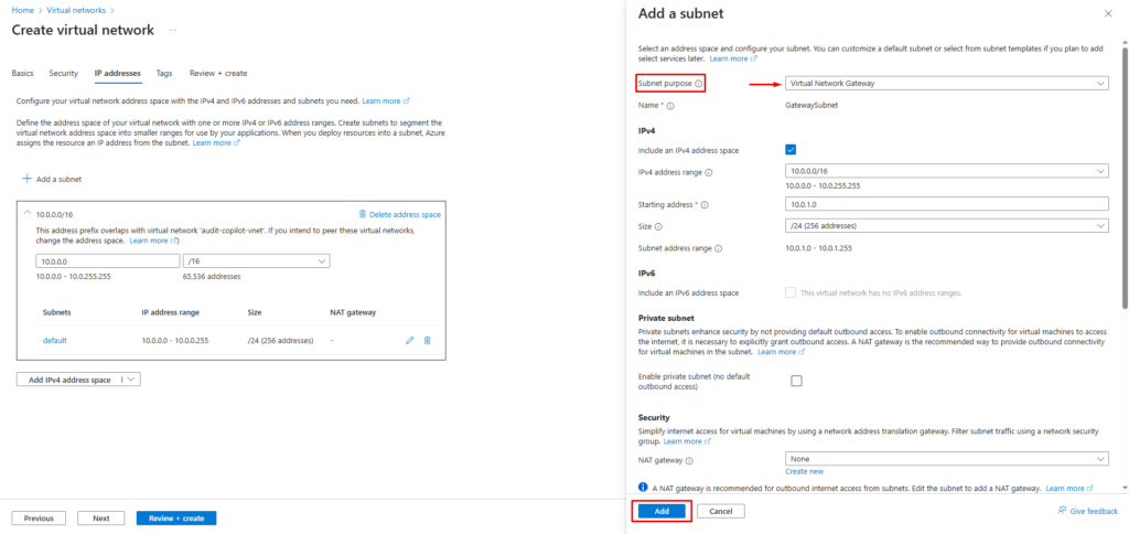
2. Setting Up the Spoke Virtual Networks — Connecting the Dots!
Now, let’s create the spokes (additional virtual networks) that connect to the hub and establish a connection between them.
This is our Spoke1:
- Go to the Azure portal and navigate to Virtual Networks.
- Choose your Subscription, Resource Group.
- Now give the name to this VNET “Spoke1”.
- Do not change anything under the Security tab for this set-up.
- In IP Addresses tab choose, IP address range the you want. (default 10.1.0.0/16)
- we don’t need to define any other specific subnet for the Spoke.
- Now simply click on review + create.
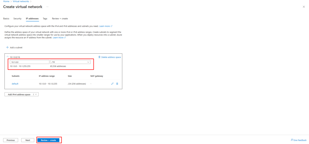
Now lets create a Spoke2 similar as Spoke1:
- Go to the Azure portal and navigate to Virtual Networks.
- Choose your Subscription, Resource Group.
- Now give the name to this VNET “Spoke2”.
- Do not change anything under the Security tab for this set-up.
- In IP Addresses tab choose, IP address range the you want. (default 10.2.0.0/16)
- we don’t need to define any other specific subnet for the Spoke.
- Now simply click on review + create.
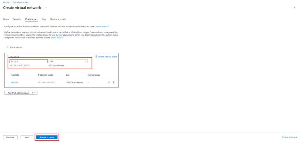
3. Build the Virtual Network Gateway — The Bridge Between Networks
What is a Virtual Network Gateway (VNG) and Its Role in the Hub-Spoke Model?
A Virtual Network Gateway (VNG) is a networking service in Azure that enables secure communication between different virtual networks, on-premises networks, or external connections through VPN or ExpressRoute. It acts as a bridge, managing encrypted traffic flow and ensuring seamless connectivity across distributed environments.
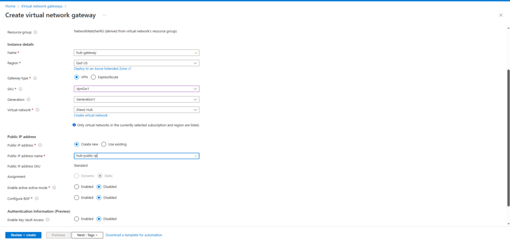
To create Virtual Network Gateway follow the below steps:
- Go to the Azure portal and navigate to Virtual Network Gateway.
- Choose your Subscription, Resource Group.
- Provide a meaningful name for the gateway.
- Select the Region (must match the hub virtual network region).
- For this setup the use the VPN gateway type.
- Now Select the preferred SKU (use the VpnGW1 for the low cost).
- Under Virtual Network, select the previously created Hub VNet.
- Ensure that a GatewaySubnet exists in the selected virtual network.
- Choose Create New to generate a public IP for the gateway.
- Give the appropriate name for the Public IP.
- Click Review + Create to validate the settings.
4. Bridging the Gap — Peering the Virtual Network Gateway to the Spokes
Why Peering Needed in the Hub-Spoke Model?
Peering is required to establish communication between the hub virtual network (where the Virtual Network Gateway is deployed) and the spoke virtual networks. Since the spokes are isolated networks created for different workloads, they cannot communicate with the hub or other spokes directly unless peering is configured.
Steps to Create Peering:
- Go to the Azure portal.
- Navigate to the Spoke1 Virtual Network.
- On the left side panel, select
Peeringsunder the Settings section. - Click on the
+ Addbutton to create a new peering. - In the “Remote virtual network summary” section:
- Give the Meaning full name in the “Peering link Name” (e.g. spoke1tohub)
- Select your subscription.
- And then select the “HUB” Vnet that we created earlier.
- In the “Remote virtual network peering settings” section:
- Allow the peered virtual network to access
spoke1→ Enable (Tick the box). - Allow the peered virtual network to receive forwarded traffic from
spoke1→ Enable (Tick the box). - Allow gateway or route server in the peered virtual network to forward traffic to
spoke1→ Enable (Tick the box). - Enable the peered virtual network to use spoke1 remote gateway or route server → Enable (Tick the box).
- Allow the peered virtual network to access
In the “Local virtual network summary” section:
- Enter Peering Link Name → Example:
spoke1toHub
- Enter Peering Link Name → Example:
- In the “Configure Local Virtual Network Peering Settings” section
- Allow
spoke1to access the peered virtual network → Enable (Tick the box). - Allow gateway or route server in
spoke1to forward traffic to the peered virtual network → Enable (Tick the box). - Enable
spoke1to use the peered virtual network’s remote gateway or route server → Enable (Tick the box).
- Allow
NOTE: Repeat the same steps for other spokes2, by changing the peering name accordingly (Example: spoke2toHub).
5. Setting Up Routing Tables — So Our Resources Can Talk
In a Hub and Spoke network architecture in Azure, route tables are essential for managing and controlling the flow of traffic between the Hub and Spoke virtual networks (VNets). The Hub network usually contains shared services like VPN gateways, firewalls, and other security appliances, while the Spoke networks host workloads like applications and databases. Route tables are created to define custom routes that force the traffic between Spoke VNets to flow through the Hub VNet for centralized security, monitoring, and connectivity. This setup enables better traffic control, improved security, and optimized network management in the Hub and Spoke topology.
Steps to Create a Route Table in Azure:
- In the search bar, type
Route tablesand select it from the search results. - Click on
+ Createto start creating a new route table. - n the Basics tab, under Subscription, select your Subscription.
- Under Resource group, select resource group.
- In the Region field, select the same region same as the Spoke1 Vnet we created.
- n the Name field, enter the name of the route table as
Spoke1RT. - Under Propagate gateway routes, select
Yesto allow propagation of routes from the gateway. - Click on
Review + Create.
NOTE: Repeat the same step to Create Route table for the Spoke2 Vnet.
Steps to Add a Route in Azure Route Table:
- Select the route table
Spoke1RT. - In the left-hand menu, click on
Routesunder the Settings section. - Click on
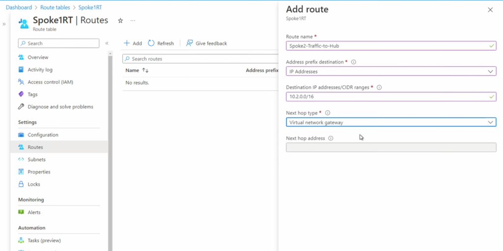
+ Addto create a new route. - In the Add route page:
- Enter
Spoke2-Traffic-to-Hubas the Route name. - Under Address prefix destination, select
IP Addresses. - In Destination IP addresses/CIDR ranges, enter the address space of Spoke2 VNet. (e.g 10.2.0.0/16 )
- In Next hop type, select
Virtual network gatewayfrom the dropdown.
- Enter
- Leave the Next hop address blank (it will be automatically picked based on the gateway configuration).
- Click on
Addto create the route
NOTE: Repeat the same steps for the Add the route in Spoke2RT. And in this route use the address space of Spoke1 Vnet.
6. Steps to Verify the Hub and Spoke Topology Connectivity
Follow the below steps to confirm that the hub and spoke topology is working as expected:
- Create a Virtual Machine (VM) in
Spoke1VNet and another VM inSpoke2VNet. - Ensure that both VMs are in their respective subnets and have a private IP assigned.
- Connect to the VM in
Spoke1VNet using Bastion or RDP/SSH. - From
Spoke1VM, try to ping the private IP of the VM inSpoke2VNet. - If the ping is successful, it confirms that traffic from Spoke1 to Spoke2 is flowing through the Hub Virtual Network Gateway using the route created in the route table.
- Similarly, you can ping from
Spoke2VM toSpoke1VM to confirm bidirectional connectivity.
This validates that the custom routes and hub-spoke network topology are configured correctly.
Conclusion
In conclusion, the Hub and Spoke architecture is a highly effective network topology that provides centralized management, improved security, and optimized resource sharing across multiple environments. It simplifies network design by allowing spokes to communicate with each other through the hub, enabling better control over traffic flow and easier implementation of shared services like firewalls, VPN gateways, and monitoring solutions
Subscribe Newsletter for more!